
Page 103 - 《橡塑技术与装备》英文版2026年2期
P. 103
PRODUCT AND DESIGN
mesh size in the sealing surface and sealing groove areas was
appropriately relaxed to 0.5 mm. However, the mesh size in
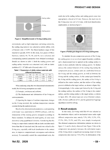
the O-ring area was set to 0.2 mm, with local densification
implemented, as shown in figure 3.
Figure 2 Simplified model of O-ring sealing area
environment, such as high temperature and strong corrosivity,
the sealing ring material was selected as nitrile rubber, with
a Poisson's ratio v=0.499. The Shore hardness range of this
Figure 3 Partial grid diagram of O-ring sealing area
material is typically 20-90. In this study, four grades of Shore
hardness, namely 60, 70, 80, and 90, were selected, and To simulate the pre-compression process of the O-ring,
corresponding material parameters were obtained accordingly. the sealing groove is set as a fixed support boundary condition,
Details are shown in table 1. Both the sealing groove and and a displacement load is applied on the sealing surface to
sealing surface materials were structural steel, with an elastic make it close perfectly with the sealing groove. To further
modulus of 2×10 MPa and a Poisson's ratio v=0.3. analyze the contact behavior of the sealing ring during the
5
Table 1 Parameters of nitrile rubber materials with compression process, contact pairs are established between
different hardnesses the O-ring and the sealing groove, as well as between the
Hardness (H A ) 60 70 80 90
E(MPa) 3.619 5.542 9.388 20.925 O-ring and the sealing surface. In the contact pair formed by
C 10 (MPa) 0.483 0.739 1.252 2.790 the O-ring and the sealing groove, the surface of the O-ring is
C 01 (MPa) 0.121 0.185 0.313 0.698
defined as the contact surface, and the surface of the sealing
When analyzing using this two-dimensional axisymmetric groove is defined as the target surface, as shown in figure 4(a).
model, the following assumptions are made: Correspondingly, in the contact pair formed by the O-ring and
(1) Isotropic, continuous and uniform; the sealing surface, the surface of the O-ring is the contact
(2) The displacement and deformation of the O-ring are surface, and the sealing surface is the target surface, as shown
centrosymmetric; in figure 4(b). All contact types are set as frictional contact,
(3) Ignoring the impact of medium temperature changes with a friction coefficient of 0.3, and the generalized Lagrange
on the O-ring material, the medium temperature remains algorithm is used for solving.
constant during the analysis process.
Based on the aforementioned parameters, a corresponding 3 Result analysis
solid model was established in ANSYS software, with the In this study, an O-ring with HA=90 was selected as
dimensions of the sealing groove designed according to the simulation object, and its mechanical states under eight
Parker standards. To enhance the mesh quality, all areas were different compression rates, namely 7.5%, 10%, 12.5%, 15%,
discretized using quadrilateral elements. Considering that the 17.5%, 20%, 22.5%, and 25%, were deeply investigated.
O-ring is a super-elastic material with an elastic modulus much The obtained compression deformation patterns are shown in
lower than that of structural steel, the mesh was refined in the figure 5. It can be clearly observed from Figure 5 that as the
O-ring area, especially with local densification in the contact compression rate gradually increases, the deformation degree
area, to improve computational convergence and solution of the O-ring shows a significant increasing trend. At lower
accuracy. To reasonably control the computational scale, the compression rates (such as 7.5%-15%), the deformation of the
Vol.52,2026 ·59·