
Page 102 - 《橡塑技术与装备》英文版2026年2期
P. 102
HINA R&P TECHNOLOGY AND EQUIPMENT
area remaining equal before and after compression. After E=6(C 10 +C 01 ) and indicating that additional correction is
compression, the short axis of the ellipse is b and the long axis required to control the error within 5% under large strain.
is a. Therefore, the short axis of the ellipse, b=R(1-ε)the initial Research on O-rings for shield machines shows that when the
circular cross-sectional area, and the compressed elliptical compression rate is between 10% and 25%, the contact stress is
2
cross-sectional area are πR , and respectively. According to the linearly correlated with strain. The linear correction form can
conservation of area πab, the long axis a of the ellipse is: control the prediction error within 7%, supporting 1+2.5ε the
π ab = π R 2 ⇒ a = R engineering applicability of the correction term. The extended
1 ε (9)
−
(3) Radius of curvature Mooney-Rivlin model further verifies the universality of the
For the compressed elliptical cross-section, contact occurs strain correction term, and its results are highly consistent with
at the vertex of the ellipse (the maximum deformation point experimental data on rubber. In summary, the strain correction
under axial compression), with a radius of curvature being: term adopted in this paper has both experimental and
R 2 theoretical support, and is well compatible with the mechanical
a 2 1 ε R (10) laws of rubber materials. Therefore, the equivalent elastic
−
∗
R = = =
b R − ) (1 ε ) 3 modulus E is:
(1 ε
−
*
1.3 Equivalent elastic modulus E =6(C 10 +C 01 ) (1+2.5ε) (14)
*
The elastic modulus E, C10, and C01 coefficients of Based on equations (1) to (14), the contact width of the
rubber can be determined based on the hardness HA of rubber O-ring is:
according to the following formula: FR ∗ d 2(C + C )ε + 3(C + 3C )ε
2
3
15.75 2.15H w = 2 * = 10 3 01 10 01
+
+
−
E = A (11) π E 12(1 ε ) (C + C 01 )(1 2.5 ) ε (15)
10
−
100 H A
C 01 =0.25C 10 (12) 2 Geometric simulation model
E=6(C 10 +C 01 ) (13)
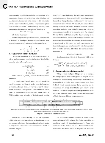
Taking a certain intelligent sliding sleeve as an example,
In the formula, C 10 and C 01 represent the Mooney-Rivlin the O-ring is placed in the sealing groove of the part, and the
parameters.
sealing type is static sealing. The sealing is achieved by the
The elastic modulus of rubber materials exhibits
deformation of the O-ring under pressure, as shown in figure
significant strain nonlinearity under large deformation, 1. The O-ring is prone to damage during assembly, and its
necessitating the introduction of correction terms to enhance
compression rate is only affected by the space reserved in the
model accuracy. Through static tensile tests on nitrile
structure. This article analyzes the sealing performance of the
rubber, a fitting was obtainedC 10 =0.115 9 MPa,C 01 =0.0.214 O-ring and studies the contact width and mechanical properties
7 MPa, validating the rationality of the basic elastic modulus of the O-ring under different compression rates.
1-Outer joint, 2-Upper joint, 3-Spindle, 4-Outer cylinder, 5-Storage chamber sub, 6-Motion sub, 7-Inner sliding sleeve, 8-Outer sliding sleeve, 9-Circular cross-
section helical compression spring, 10-O-shaped rubber sealing ring
Figure 1 2D model of smart slide cover
Given that both the O-ring and the sealing groove The finite element simulation analysis of the O-ring was
exhibit axisymmetric characteristics, to simplify calculations conducted using ANSYS software. The O-ring selected for the
and enhance efficiency, the three-dimensional solid model simulation was a 2-331 standard part produced by Parker, with
is simplified to a two-dimensional axisymmetric model, as an inner diameter of 56.52 mm and a diameter of 5.33 mm.
illustrated in figure 2. Considering the characteristics of the petroleum downhole
·58· Vol.52,No.2