
Page 72 - 《橡塑技术与装备》英文版2026年2期
P. 72
HINA R&P TECHNOLOGY AND EQUIPMENT
By reading and fitting the three sets of mold clamping
force-displacement data obtained through manual mold
opening and closing, the data is input into the configuration
software. The least squares method is used to obtain the mold
clamping force-displacement curve data. The screen script
will obtain the target position corresponding to the target mold
clamping force based on the mold clamping force-displacement
curve. The automatic mold adjustment program will compare
the current position value with the target position value based
on the target position, drive the mold adjustment motor, adjust
the current position to approach the target position, and thus
achieve the one-click mold adjustment function.
3.3 Key electrical procedures
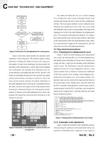
Figure 5 Flowchart of mold adjustment for curing press 3.3.1 Clamping force-displacement curve
Figure 7 shows the mold clamping force-displacement
Figure 6 shows the control interface for automatic mold
adjustment of the curing press. The interface requires setting curve script. By obtaining three sets of mold clamping force
and displacement information through mold opening and
parameters including the number of teeth on the large gear,
closing, the data is input into the automatic mold adjustment
the number of teeth on the small gear, the thread pitch, the
control system. The fitted data is read and substituted into
maximum mold clamping force, and the target mold clamping
force information. By inputting these information into the equations (4) and (5). Using configuration software, a least
squares method script is written to calculate the coefficients
system interface and writing them into the PLC, the PLC will
of the linear equation, thus creating a mold clamping force-
obtain the relationship between the rotary encoder's turn signal
and the mold position according to formula (1). Since the displacement visualization curve in the control interface. The
interface script can also calculate the target position based on
rotary encoder directly measures the rotation information of
the user-set target mold clamping force, write the value into
the mold adjustment motor, knowing the relationship between
the rotary encoder's turn signal and the mold position means the PLC's automatic mold adjustment control system, read the
current position from the PLC in real time, and calculate the
knowing the relationship between the mold position and the
current mold clamping force, achieving efficient and visual
number of rotations of the mold adjustment drive motor. The
program will upload the current position information to the human-machine interaction.
interface in real time.
Figure 7 Clamping force-displacement curve script
3.3.2 Automatic mold adjustment
Figure 8 shows the automatic mold adjustment program.
Figure 6 Automatic mold adjustment control interface of After pressing the automatic mold adjustment button, the
curing press
automatic mold adjustment completion status signal is
·28· Vol.52,No.2