
Page 70 - 《橡塑技术与装备》英文版2026年2期
P. 70
HINA R&P TECHNOLOGY AND EQUIPMENT
of the upper fixed plate in the program. When changing molds indicates that both the pressure mechanism and the mold
or readjusting parameter data, you can freely choose whether undergo elastic deformation during the mold clamping process,
to "zero" in the program to set the zero point value of H. and the force and deformation of the two are linearly related.
2.3 Force measurement principle For mechanical curing presses, the main parts subjected
The acquisition of clamping force for a mechanical tire to force and deformation during mold clamping are the
shaping and curing press is primarily measured through a connecting rod, crossbeam, and mold. The force measurement
force-measuring mechanism at both ends of the connecting mechanism calculates the mold clamping force by measuring
rod. When the connecting rod operates, it is subjected to the deformation of the connecting rod.
tension, typically experiencing a deformation of 0.3-0.7mm. Based on the above analysis, the mold clamping force-
The main component of the force-measuring mechanism, the deformation diagram and force measurement mechanism in
tonnage gauge, is modified from a micrometer. By measuring the rubber machinery manual are both based on the principle
the slight elastic deformation of the connecting rod through the of elasticity. The overall force transmission mechanism is
tonnage gauge and combining it with Hooke's law, the tensile relatively stable due to mechanical structural deformation,
force of the connecting rod can be determined. The relationship and the entire assembly dimensional chain is clear. Therefore,
between the deformation and tensile force measured by the the mold clamping force and the displacement of the pressure
force-measuring mechanism is as follows: mechanism or model also exhibit a linear relationship,
ΔL=σ×L/E (2) which can be described by a linear equation. The mold
σ=F/A (3) clamping force-displacement curve fitting of the automatic
In the formula, L represents the distance between the two mold adjustment device in this article is constructed based
axial holes of the connecting rod, E denotes the elastic modulus on the linear relationship between mold clamping force and
of the connecting rod, F signifies the tensile force applied displacement. The mold clamping force values taken are from
to the connecting rod, and A stands for the cross-sectional the tonnage table of the force measurement mechanism, and the
area of the main plate of the connecting rod. By utilizing displacement values obtained are from the position of the upper
the aforementioned formulas (2) and (3), the tensile force fixed plate measured by a rotary displacement encoder. By
on the connecting rod can be determined, and subsequently, reading three sets of mold clamping force-displacement (F i , H i )
the clamping force in the tonnage table can be calculated. data, the least squares method is used to achieve a linear fitting
From the above, it can be concluded that traditional clamping relationship between mold clamping force and displacement,
force is obtained through the measurement of connecting rod and the linear equation F=aH+b is solved to fit the relationship
deformation, based on the principle of elastic deformation, between mold clamping force and displacement.
which is the linear relationship between force and deformation. There are currently three sets of data points, assumed
to be (F 1 , H 1 ), (F 2 , H 2 ), and (F 3 , H 3 ). If these three points are
collinear, then there exists an exact solution; however, the
three points typically measured are not strictly collinear. In this
case, the Least Squares Method is needed to find the best-fit
straight line. The Least Squares Method adopts the principle of
minimizing the sum of squared errors to obtain the objective
function. In the Least Squares Method for univariate linear
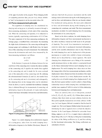
Figure 4 Curing press mold clamping force-deformation fitting, suppose a set of N (x, y) sample data is subjected to
diagram
linear fitting with y=ax+b. The key to fitting lies in determining
Figure 4 is a mold clamping force-deformation diagram the values of the fitting coefficients (a, b), and then solving
of a curing press, taken from the mold clamping force- for the functional relationship. The fitting coefficients are
deformation diagram in the Rubber Machinery Manual. It calculated as follows:
·26· Vol.52,No.2