
Page 82 - 《橡塑技术与装备》英文版2026年2期
P. 82
HINA R&P TECHNOLOGY AND EQUIPMENT
that b 1 =b 2 . At this point, it can be determined that c 1 =c 2 , that mm respectively (see Figures 7 and 8). Record the light line
is, the installation surface of the marking device is parallel to scale values at these two positions, adjust the laser light so that
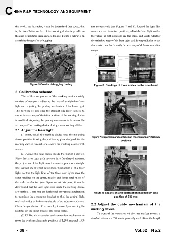
the axes of multiple drum surface tooling. Figure 5 below is an the values at both positions are the same, and verify whether
actual site image after debugging. the emission angle of the laser light path is perpendicular to the
drum axis, in order to verify the accuracy of different detection
ranges.
Figure 5 On-site debugging tooling Figure 6 Readings of three scales on the drumhead
2 Calibration scheme
The calibration process of the marking device mainly
consists of two parts: adjusting the internal straight-line laser
light and adjusting the guiding mechanism of the laser light.
The purpose of adjusting the straight-line laser light is to
ensure the accuracy of the initial position of the marking device
is qualified. Adjusting the guiding mechanism is to ensure the
accuracy of the marking device during movement is qualified.
2.1 Adjust the laser light
(1) First, install the marking device onto the mounting
Figure 7 Expansion and contraction mechanism at 1200 mm
frame, position it using the positioning plate designed for the position
marking device bracket, and secure the marking device with
screws.
(2) Adjust the laser lights inside the marking device.
Since the laser light path projects in a fan-shaped manner,
the projection of the light onto the scale appears as a straight
line. Adjust the internal adjustment mechanism of the laser
lights so that the light lines of the three laser lights have the
same readings on the upper, middle, and lower steel rulers of
the scale mechanism (see Figure 6). At this point, it can be
determined that the laser light lines inside the marking device
are vertical. Then, use the horizontal movement mechanism Figure 8 Expansion and contraction mechanism at a
to translate the debugging bracket so that the central light position of 500 mm
mark coincides with the central scale of the adjustment device.
Check the parallelism of the laser light beams by observing the 2.2 Adjust the guide mechanism of the
marking device
readings on the upper, middle, and lower scales.
To control the operation of the line marker motor, a
(3) Utilize the expansion and contraction mechanism to
standard distance of 50 mm is generally used. Since the length
move the scale mechanism to positions of 1,200 mm and 1,500
·38· Vol.52,No.2