
Page 83 - 《橡塑技术与装备》英文版2026年2期
P. 83
TEST AND ANALYSIS
of each slider in the internal guiding mechanism of the line needs to operate continuously for more than 24 hours under
marker is approximately 60 mm, to ensure accurate positioning standard procedures.
of the laser light line, it is recommended that the standard (3) After operation, the marking device needs to recheck
inspection distance be less than the slider size. Move in the previously inspected content. Ensure that the deviation
sections from 50mm to the maximum travel of the light marker between the recheck results and the initial inspection results
to inspect its positioning accuracy. does not exceed 50% of the maximum allowable error, and that
Since the straight line laser light of the marking device is the recheck results meet the required accuracy for the beacon.
installed on the guiding module for operation, any directional
deviation of the guiding module will affect the direction of the 3 Process optimization
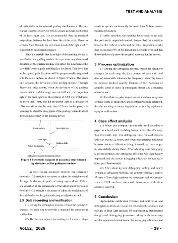
laser light's optical path, resulting in a deviation. This deviation (1) During the debugging process, record the parameter
in the optical path direction will be proportionally magnified changes for each step, the data content of each unit, and
onto the scale surface, as shown in figure 9 below. The green develop reasonable solutions for frequently occurring issues
line indicates the deviation of the guiding module. Through to improve product quality. Emphasize the recording of
theoretical calculations, when the deviation of the guiding sporadic issues to assist in subsequent design and debugging
module within a slider range exceeds 0.05 mm, the projection optimization.
light of the laser light line at a distance of 1200 mm will deviate (2) Establish a regular inspection and maintenance system
by more than 1mm, and the projection light at a distance of for laser lights to ensure they are in optimal working condition,
1500 mm will deviate by more than 1.25 mm. At this point, it is thereby avoiding accuracy degradation caused by equipment
necessary to adjust the straightness of the guiding module to adjust aging or malfunction.
the marking accuracy of the marking device.
4 Case effect analysis
(1) When our company previously used coordinate
paper as a benchmark to debug beacon units, the efficiency
was extremely low. The debugging time for each beacon
unit was around 12 hours, and when encountering individual
beacons that were difficult to debug, it would take even longer
to successfully debug them. After adopting new debugging
tools and methods, the debugging efficiency was significantly
Figure 9 Schematic diagram of accuracy error caused improved, and the current debugging efficiency has reached 8
by deviation of the guidance module hours per 2 beacon units.
(2) After adopting new debugging tooling and newly
If the positioning accuracy exceeds the tolerance formulated debugging methods, our company applied a total of
(typically ±0.5 mm), it is necessary to adjust the straightness of 87 units of laser light markers on equipment and at customer
the upper busbar on the guide rail using copper shims. If there sites in 2024, and no issues with inaccurate calibration
is a deviation in the dimensions of the upper and lower scales accuracy occurred.
(typically ±0.5 mm), it is necessary to adjust the straightness of
the side busbar on the guide rail using an adjustment tool. 5 Conclusion
2.3 Data recording and verification Appropriate calibration fixtures and calibration and
(1) During the debugging process, record the parameter debugging methods are crucial for enhancing the accuracy and
changes for each step to provide a standard for subsequent stability of laser light markers. By implementing standardized
verification. design and debugging processes, along with necessary
(2) The beacon adjusted according to the above steps regular equipment maintenance, the debugging efficiency and
Vol.52,2026 ·39·