
Page 80 - 《橡塑技术与装备》英文版2026年2期
P. 80
HINA R&P TECHNOLOGY AND EQUIPMENT
convenient debugging methods. Now, we will introduce the and there is no need to move the marker during subsequent
specific debugging process. calibration.
(2) The debugging device is primarily designed to
1 Structural design and construction simulate the working conditions of a tire building machine. It
design is equipped with a lateral movement mechanism for horizontal
1.1 Mechanism design of tooling movement, a contraction and expansion mechanism for
Regarding the purpose of debugging the laser marker, it controlling the calibration distance, and a directly observable
is primarily to provide precise dimensional reference for the drum surface assembly. These three mechanisms are
laser marker during the operation of the building machine. sequentially connected, with the first two primarily responsible
Therefore, the design of the debugging tooling should for controlling the debugging position. The drum surface
strive to replicate the actual working conditions of the laser tooling can better simulate the shape of the forming drum on
marker as closely as possible. This debugging tooling mainly the building machine.
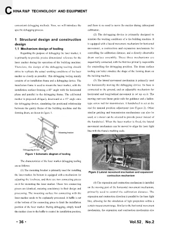
consists of an installation frame and a debugging device. The (3) The lateral movement mechanism is primarily used
installation frame is used to mount the laser marker, with the for horizontally moving the debugging device. Its base is
installation surface forming a 45° angle with the horizontal connected to the ground, and an adjustable mechanism for
plane and parallel to the debugging frame. The calibrated horizontal and longitudinal movement is set up on it. The
marker is projected obliquely downward at a 45° angle onto moving part uses linear guide rails for guidance and a ladder-
the debugging device, simulating the positional relationship type screw rod for transmission. A handwheel is set at the
between the gantry frame of the building machine and the end for manual position adjustment (see Figure 2). Other
forming drum, as shown in figure 1. similar guiding and transmission mechanisms can also be
used, or a motor can be selected to provide power instead of
the handwheel. When the laser marker is fixed, the lateral
movement mechanism can be moved to align the laser light
line with the frame's marking scale.
Figure 1 Schematic diagram of tooling
The characteristics of the laser marker debugging tooling
are as follows:
(1) The mounting bracket is primarily used for installing
Figure 2 Lateral movement mechanism and expansion/
the laser marker. Its bottom is equipped with a mechanism for contraction mechanism
adjusting the levelness, and there are two connecting pieces
on it for mounting the laser marker. These two connecting (4) The expansion and contraction mechanism is installed
pieces are identical, ensuring consistency in their design and on the moving part of the horizontal movement mechanism,
processing. The mounting surface for connecting with the primarily used to control the calibration distance. The
laser marker needs to be coplanarly processed. A baffle is set expansion and contraction direction is parallel to the laser light
at the bottom of the connecting piece to limit the installation line, allowing for the simulation of light projection within a
position of the laser marker. During debugging, simply install certain measurement range. Similar to the horizontal movement
mechanism, the expansion and contraction mechanism also
the marker close to the baffle to control its installation position,
·36· Vol.52,No.2